« Povray/City » : différence entre les versions
| (16 versions intermédiaires par le même utilisateur non affichées) | |||
| Ligne 1 : | Ligne 1 : | ||
== Overview == | == Quick Start == | ||
The City Generator Include File builds cities using a combination of include, macro, and object files to create cities, towns, etc. Each of these files support different options to change the sort of city that is created, and you can design your own macro and/or object files to create entirely new and different cities. | |||
The main include file, City.inc "maps out" the city, and includes options to control the placement of streets and city blocks. The default macro file, City.mcr then builds the city by placing objects to create streets and pavements, traffic, and buildings. These objects are defined in the city object files, which include simple vehicles, street lamps, bus stops, traffic lights, and a selection of office, hotel, and apartment buildings. The buildings are created by stacking single levels on top of each other, so that everything from one-storey lowrises to skyscrapers can be generated. | |||
To create a city using the default macro and object files, you simply declare all the options you want to use, and then include the City.inc file, eg: | |||
<syntaxhighlight lang="povray"> | |||
#declare traffic_spacing = 4; | |||
#declare traffic_lanes = 2; | |||
#declare city_block_count = <10, 5, 0>; | |||
#include "CITY.INC" | |||
</syntaxhighlight> | |||
If you want to use custom object files, you must include these before including City.inc, eg: | |||
<syntaxhighlight lang="povray"> | |||
#include "Future.obj" | |||
#include "HoverVehicles.obj" | |||
#include "CITY.INC" | |||
</syntaxhighlight> | |||
This would create a city using the buildings and vehicles defined in the two *.OBJ files, rather than the default object files. To use custom macro files, you should use the city_macro_file option. | |||
Note that custom object and macro files may support their own options for changing the city characteristics, and may not necessarily support all of the options used by the default files (listed in the following sections). You should check the documentation that comes with the custom files to be sure of which options are supported. | |||
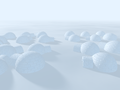
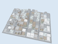
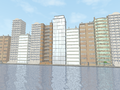
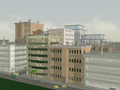
<gallery> | |||
Fichier:PovrayCityArctic.png|Arctic Village | |||
Fichier:PovrayCityScap.png|Sky view | |||
Fichier:PovrayCityWaterlin.png|City near water | |||
Fichier:PovrayCityDefault.png|Default City | |||
</gallery> | |||
{| class="wikitable" | |||
! Option Name !! Type/Description !! Default | |||
|- | |||
| colspan="3" | '''GENERAL OPTIONS''' | |||
|- | |||
| debug_progress || Prints progress info. to debug stream || false | |||
|- | |||
| city_macro_file || Name of macro file to use when creating city || "CITY.MCR" | |||
|- | |||
| colspan="3" | '''CITY SIZE OPTIONS''' | |||
|- | |||
| city_block_count || Vector or float; blocks along x and z || <nowiki><2, 0, 2></nowiki> | |||
|- | |||
|- | |||
| buildings_per_block || Vector or float; buildings along x and z || <nowiki><3, 0, 2></nowiki> | |||
|- | |||
| street_width || Total width of streets (POV units) || 10 | |||
|- | |||
| pavement_width || Width of pavement around edges of blocks || 4 | |||
|- | |||
| building_width || Width of each edge of buildings || 25 | |||
|- | |||
| building_gap || Gap between each building || 2 | |||
|- | |||
| city_tileable || If true, +x and +z edges not created || false | |||
|- | |||
| city_transform || transform {} option for entire city || - | |||
|- | |||
| city_corners || Not declarable; returns x-z bounding values || - | |||
|- | |||
| colspan="3" | '''CITY MACRO FILE OPTIONS''' | |||
|- | |||
| city_seed | Seed for all random aspects of city || 0 | |||
|- | |||
| min_building_height || Minimum height of buildings (POV units) || 12.5 | |||
|- | |||
| max_building_height || Maximum height of buildings (POV units) || 50 | |||
|- | |||
| building_height_falloff || Falloff rate from city centre to edges || 2 | |||
|- | |||
| building_height_turb || Randomness of building heights || 0.5 | |||
|- | |||
| pavement_height || Height of pavement from street (POV units) || 0.15 | |||
|- | |||
| traffic_spacing || Minimum distance between vehicles (POV units) || 10 | |||
|- | |||
| traffic_lanes || Traffic Lanes in each direction || 1 | |||
|- | |||
| traffic_width || Width of each lane of traffic (POV units) || 3 | |||
|- | |||
| colspan="3" | '''CITY OBJECT FILE OPTIONS''' | |||
|- | |||
| city_night || If true creates lit windows and light cones || false | |||
|- | |||
| windows_lit || Proportion of windows lit || 0.33 | |||
|- | |||
| windows_blend || Blend from lit windows to unlit windows || 0.25 | |||
|- | |||
| city_right_hand_drive || True/false || false | |||
|- | |||
| max_building_types || Increase if using many different object files || 100 | |||
|} | |||
=== Included files === | |||
* Include Files | |||
** '''CITY.INC''' - City Generator include file | |||
** '''CITY.MCR''' - Default City Generator macro file | |||
** '''FILECITY.MCR''' - File output city macro file (see beginning of file) | |||
* Object Files | |||
** '''DEFAULT.OBJ''' - Default city objects file | |||
** '''VEHICLES.OBJ''' - City vehicles file | |||
** '''HOTELS.OBJ, FLATS.OBJ, OFFICES.OBJ''' - Default city building files | |||
* Sample | |||
** '''DEFCITY.POV''' - Sample city animation | |||
** '''WATERLIN.POV''' - Sample city scene | |||
** '''ARCTIC.POV''' - Sample custom city macros scene | |||
** '''CITYSCAP.POV''' - Sample animation using FILECITY.MCR | |||
** '''TEMPLATE.MCR''' - Template city macro file | |||
== Options Reference == | |||
=== City Include File Options === | |||
The following options are for use with City.inc itself, and will alter the city regardless of any custom macro and object files (see above). The City Generator creates cities in the x-z plane (with the y-axis pointing skywards). The city is constructed from a grid of city blocks (containing the buildings), separated by streets running in the x and z directions. The city is centred on the origin, with the overall size being determined by the various measurements below (see city_corners). The scale used is arbitrary, and will generally be determined by the city object files you use. In the case of the default object files, one unit is approximately equal to one metre. | |||
* '''debug_progress'''<br>Declaring this option to true will allow you to view the activities of the City Generator Include File as it creates the city. The information sent to POV-Ray's debug stream includes the overall size of the city (in the x-z plane). This can be very useful when parsing large scenes, or for troubleshooting while you are designing your own custom city macro and/or object files. | |||
* '''city_macro_file'''<br>This option sets the name of the file which contains the macros you want City.inc to construct the city with. By default, the City.mcr file is used. Note that you do not have to declare this option if the city macros are defined directly within your POV file (see the example scenes provided with the City Generator). | |||
* '''city_block_count'''<br> This option sets the number of city blocks generated, each city block being surrounded by pavements and streets. The option can be declared as a vector, with the x-component setting the number of blocks generated along the x-axis, and the y or z-component setting the number of blocks in the z direction, eg:<syntaxhighlight lang="povray">#declare city_block_count = <6, 4, 0>;</syntaxhighlight>This creates a city made up of 6 x 4 blocks (for a total of 24 city blocks). You can also set this option to a single integer, which will generate the same number of blocks in both the x and z directions, eg:<syntaxhighlight lang="povray">#declare city_block_count = 6;</syntaxhighlight>This creates 36 city blocks. The default value for city_block_count is 2 x 2 blocks. | |||
* '''buildings_per_block'''<br>This options sets the number of buildings created on each city block. Like the city_block_count option, either a vector or float can be used, eg:<syntaxhighlight lang="povray">#declare buildings_per_block = 3;</syntaxhighlight>will create nine buildings on each city block (3 in the x direction by 3 in the z direction). The default value for buildings_per_block is 3 x 2 buildings. | |||
* '''street_width'''<br>This option sets the width of the streets separating each city block. Note that if the default City.mcr file is used, this value will be overwritten by the traffic settings (which you should use instead of the street_width option). The default value (when City.mcr is not used) is 10 units. | |||
* '''pavement_width'''<br>This option sets the width of the pavement surrounding each city block (on all four sides). The default value is 4 units. | |||
* '''building_width'''<br>This option sets the width and depth of each building in the city. The default value is 25 units. | |||
* '''building_gap'''<br>This option sets the gap between adjacent buildings (ie. the width of the city alley ways). The default value is 2 units. | |||
* '''city_tileable'''<br>Normally the entire city is surrounded by streets (around the perimeter of the rectangle that bounds the city). Setting this option to true will stop streets being created along the +x and +z edges of the city, so multiple copies of the city can be tiled together, eg: | |||
<syntaxhighlight lang="povray"> | |||
#declare city_tileable = true; | |||
#declare CityTile = #include "CITY.INC" | |||
object {CityTile} #declare CitySize = city_corner2 - city_corner1; | |||
object {CityTile translate x*CitySize} object {CityTile translate -x*CitySize} | |||
object {CityTile translate z*CitySize} object {CityTile translate -z*CitySize}</syntaxhighlight> | |||
* '''city_transform'''<br>This option sets the transformation you want to be applied to the entire city, eg. to convert the city to a right-handed coordinate system:<syntaxhighlight lang="povray">#declare city_transform = transform {rotate x*90 scale <-1, 1, 1>}</syntaxhighlight> | |||
* '''city_corners'''<br>Although not an option you can set, the city_corner1 and city_corner2 vectors will be declared by City.inc when you include it. Both vectors lie in the x-z plane (no height values are included), and they are particularly useful when creating tiled cities (see city_tileable). You can also use the city_corner values to place other objects, light sources, the camera, etc. Note that the value is not affected by any city_transform you may have declared, so you should take this into account if you have transformed the city in any way. | |||
=== City Macro File Options === | |||
The options in this section are for use with City.mcr, the default macro file used by City.inc. | |||
* '''city_seed'''<br>This option sets the random seed value used to generate the city, and can be changed to generate different arrangements of vehicles and buildings. The default city_seed is 0, and any positive or negative integer can be used (within POV-Ray's numerical limits). | |||
* '''min_building_height''' and '''max_building_height'''<br>These options set the minimum and maximum heights (in units) of the buildings created in the city. The default values are half of the building_width, and double the building_width (ie. the buildings are between half and twice as high as they are wide). Normally, the highest buildings are created in the centre of the city, with shorter buildings at the edges (although the building_height_turb option will alter this somewhat). | |||
* '''building_height_falloff'''<br>This option controls how the building height changes from the centre of the city to the edges. A value of 1 would indicate a linear falloff so a straight line could be drawn from the top of the high buildings in the middle of the city to the lower buildings at the edges. Higher values give more low buildings than high buildings, while values lower than one give more high buildings than low buildings. The default building_height_falloff is 2 | |||
* '''building_height_turb'''<br>This option sets the randomness of the building heights. When set to 0, the building heights are controlled only by the building_height_falloff value, giving the city a very regular look. Good values generally range from 0 to 1, and the default building_height_turb is 0.5 | |||
* '''pavement_height'''<br>This value sets the height of the pavement (in the +y direction, where the streets sit at y = 0). The default pavement_height is 0.15 units. | |||
* '''traffic_spacing'''<br>This value controls the minimum distance between vehicles on the city streets. Setting this option to zero stops the macro file from creating vehicles altogether. The default traffic_spacing is 10 units. | |||
* '''traffic_lanes'''<br>This option sets the number of lanes of traffic created along the city streets, in one direction (eg. a value of 3 would create six lanes, three in each direction). The default traffic_lanes value is 1. | |||
* '''traffic_width'''<br>This value sets the width of one traffic lane. This option is used in combination with the traffic_lanes value to calculate the width of the streets (which overrides any street_width option you may have declared). The default traffic_width value is 3 units (which gives a default street_width of 9 units, allowing for one lane width of curb space). | |||
=== City Object File Options === | |||
The options in this section control the objects defined in the default city object files (see Installation). Other city object files may not necessarily support any or all of these options. | |||
* '''city_night'''<br>Setting this option to true turns on the night features of the City Generator default object files, including lit building windows and visible lights on street lamps and traffic. | |||
* '''windows_lit'''<br>If city_night is enabled, you can use this option to set the proportion of building windows that are lit. A value of zero indicates that no windows are lit, while a value of 1 indicates that all windows are lit. The default windows_lit value is 0.33 (ie. one-third of the windows are lit). | |||
* '''windows_blend'''<br>This option controls the transition between lit and unlit windows. A value of 0 indicates no blending, so that individual windows are either completely lit or not lit at all. A value of 1 indicates that all the windows lie somewhere between the two extremes. The default windows_blend value is 0.25 | |||
* '''city_right_hand_drive'''<br>If the traffic_spacing option is used to generate vehicles on the city streets, you can set this option to true to make the vehicles drive on the right-hand side of the streets. | |||
* '''max_building_types'''<br>As detailed above, you can use custom city object files simply by including them before including City.inc. This option sets the maximum number of building types you can use to generate the city, either by including building object files or by defining buildings directly within your POV file. The default value of 100 means you will probably never have to worry about this option, but you can increase this number if required (or decrease it to save a small amount of memory). | |||
== Design Guide == | |||
=== Overview === | |||
The documentation for the City Generator Include File explains the basic structure and usage of the include file package. This document details the guidelines to follow when you create your own custom city macro and object files. | The documentation for the City Generator Include File explains the basic structure and usage of the include file package. This document details the guidelines to follow when you create your own custom city macro and object files. | ||
| Ligne 7 : | Ligne 164 : | ||
City macro files, on the other hand, allow you to completely redefine not only the objects that the city is constructed from but also the way in which the objects are assembled. For example, you could design city macros that construct buildings directly (rather than simply copying a predefined object), ensuring that no two buildings (or vehicles, or streets, etc.) in the city are alike. Or, you could design macros that animate some or all of the city in various ways. | City macro files, on the other hand, allow you to completely redefine not only the objects that the city is constructed from but also the way in which the objects are assembled. For example, you could design city macros that construct buildings directly (rather than simply copying a predefined object), ensuring that no two buildings (or vehicles, or streets, etc.) in the city are alike. Or, you could design macros that animate some or all of the city in various ways. | ||
== Designing City Object Files == | ==== Designing City Object Files ==== | ||
City object files can be designed in two basic ways: they can contain all the objects required to build a city, or they can contain a selection of objects (say, a set of vehicles, or a single building). The second type of file can then be used in conjunction with other similar object files, so you (or people you distribute your object files to) can build a library of object files and combine them in different ways. | City object files can be designed in two basic ways: they can contain all the objects required to build a city, or they can contain a selection of objects (say, a set of vehicles, or a single building). The second type of file can then be used in conjunction with other similar object files, so you (or people you distribute your object files to) can build a library of object files and combine them in different ways. | ||
| Ligne 15 : | Ligne 172 : | ||
Also, while the scaling of objects and textures is up to you (depending on the options you use with City.inc and City.mcr such as building_width, pavement_height, etc.) you may find it best to use the default scale of approximately 1 unit = 1 metre. This will ensure that you can easily share your object files with others. | Also, while the scaling of objects and textures is up to you (depending on the options you use with City.inc and City.mcr such as building_width, pavement_height, etc.) you may find it best to use the default scale of approximately 1 unit = 1 metre. This will ensure that you can easily share your object files with others. | ||
=== Basic City Object Files === | ==== Basic City Object Files ==== | ||
The minimum requirements for a stand-alone object file are very simple: all you need to declare are a texture to be used for the streets and a texture for the pavements, plus a value telling City.mcr not to use the default objects, eg: | The minimum requirements for a stand-alone object file are very simple: all you need to declare are a texture to be used for the streets and a texture for the pavements, plus a value telling City.mcr not to use the default objects, eg: | ||
| Ligne 39 : | Ligne 196 : | ||
At intersections, two copies of the texture will be layered on top of each other at 90 degree angles. | At intersections, two copies of the texture will be layered on top of each other at 90 degree angles. | ||
=== Pavement Objects === | ==== Pavement Objects ==== | ||
The next (optional) step is to place objects on the city pavements, which might include things like street lamps, traffic lights, bus stops, fire hydrants, and pedestrians. To define the objects, you need to declare arrays containing the object definitions themselves, the offsets of the objects from the edge of the pavement, the spacing between adjacent objects, and the randomness of this spacing. These arrays will be used to place objects on all four sides of each pavement, with the objects rotated accordingly. | The next (optional) step is to place objects on the city pavements, which might include things like street lamps, traffic lights, bus stops, fire hydrants, and pedestrians. To define the objects, you need to declare arrays containing the object definitions themselves, the offsets of the objects from the edge of the pavement, the spacing between adjacent objects, and the randomness of this spacing. These arrays will be used to place objects on all four sides of each pavement, with the objects rotated accordingly. | ||
| Ligne 73 : | Ligne 230 : | ||
The phone box measures 1.5 x 2.5 metres, and is 1 metre from the street. The spacing value of zero means that only one phone box will be created along each side of the pavement. Also, the turbulence value of 100 means that the box may be between 5 and 105 metres from the street corner. If the offset distance calculated for a particular box is greater than the length of the pavement, no box will be placed along that side of the pavement (a useful feature when you don't necessarily want a particular object on every pavement). | The phone box measures 1.5 x 2.5 metres, and is 1 metre from the street. The spacing value of zero means that only one phone box will be created along each side of the pavement. Also, the turbulence value of 100 means that the box may be between 5 and 105 metres from the street corner. If the offset distance calculated for a particular box is greater than the length of the pavement, no box will be placed along that side of the pavement (a useful feature when you don't necessarily want a particular object on every pavement). | ||
=== Vehicle Objects === | ==== Vehicle Objects ==== | ||
City vehicle objects are created similar to the pavement objects, with arrays defining the objects and the minimum space required for each vehicle. To create the vehicles you should again imagine a street running along the z-axis. The vehicles should be centred on the origin, with the necessary parts of the object touching the ground at y = 0. If the front of the vehicles point in the +z direction, the vehicles will be placed on the left-hand side of the streets; vehicles pointing in the -z direction will be placed on the right-hand side of the streets. To make your object file support both arrangements, you can include an option similar to that used in the default VEHICLES.OBJ file, eg: | City vehicle objects are created similar to the pavement objects, with arrays defining the objects and the minimum space required for each vehicle. To create the vehicles you should again imagine a street running along the z-axis. The vehicles should be centred on the origin, with the necessary parts of the object touching the ground at y = 0. If the front of the vehicles point in the +z direction, the vehicles will be placed on the left-hand side of the streets; vehicles pointing in the -z direction will be placed on the right-hand side of the streets. To make your object file support both arrangements, you can include an option similar to that used in the default VEHICLES.OBJ file, eg: | ||
| Ligne 89 : | Ligne 246 : | ||
</syntaxhighlight> | </syntaxhighlight> | ||
Setting the city_vehicle_spacing values to the length of each vehicle along the z-axis ensures that vehicles don't overlap incorrectly, even when spaced closely together using the traffic_spacing option. | Setting the city_vehicle_spacing values to the length of each vehicle along the z-axis ensures that vehicles don't overlap incorrectly, even when spaced closely together using the traffic_spacing option. | ||
=== Building Objects === | ==== Building Objects ==== | ||
The building objects are the most complicated of the city objects, with up to ten arrays of objects, textures, and values possible for a single building. In addition, a stand-alone object file must also declare a set of values that tell City.mcr which arrays to use for which buildings. The good news is that the DEFAULT.OBJ file can be used to initialise the arrays and the values for a custom building objects file, by placing this line at the beginning of the file: | The building objects are the most complicated of the city objects, with up to ten arrays of objects, textures, and values possible for a single building. In addition, a stand-alone object file must also declare a set of values that tell City.mcr which arrays to use for which buildings. The good news is that the DEFAULT.OBJ file can be used to initialise the arrays and the values for a custom building objects file, by placing this line at the beginning of the file: | ||
| Ligne 109 : | Ligne 266 : | ||
* '''build_texture''' and '''build_fit_texture'''<br>Adding the build_texture value to the building options allows you to declare a building_texture that will be applied to any of the building objects that are not otherwise textured, eg:<syntaxhighlight lang="povray">#declare building_texture[building_types] = texture {pigment {rgb 0.4}}</syntaxhighlight>The texture is applied after the building has been rotated and translated into place, so the texture patterns on any two of the same type of buildings in different parts of the city will be different. In some cases, though, this may mean the texture is applied to the building incorrectly (eg. if you are using carefully aligned image/texture maps). For these sorts of textures, you should add the build_fit_texture value to the building options instead of the build_texture option. The declared building_texture will then be scaled, rotated, and translated with the building, so the alignment remains correct. | * '''build_texture''' and '''build_fit_texture'''<br>Adding the build_texture value to the building options allows you to declare a building_texture that will be applied to any of the building objects that are not otherwise textured, eg:<syntaxhighlight lang="povray">#declare building_texture[building_types] = texture {pigment {rgb 0.4}}</syntaxhighlight>The texture is applied after the building has been rotated and translated into place, so the texture patterns on any two of the same type of buildings in different parts of the city will be different. In some cases, though, this may mean the texture is applied to the building incorrectly (eg. if you are using carefully aligned image/texture maps). For these sorts of textures, you should add the build_fit_texture value to the building options instead of the build_texture option. The declared building_texture will then be scaled, rotated, and translated with the building, so the alignment remains correct. | ||
=== Building Window Options === | ==== Building Window Options ==== | ||
Although the above options are enough to design highly complex buildings, you are likely to be faced with problems if you want to create night scenes containing buildings with lit and unlit windows. Making the windows part of the building_details object would mean that every storey would have exactly the same arrangement of windows, while including the windows in the texture would probably require large image maps for a decent result, and every copy of the same building would have the same window arrangement. | Although the above options are enough to design highly complex buildings, you are likely to be faced with problems if you want to create night scenes containing buildings with lit and unlit windows. Making the windows part of the building_details object would mean that every storey would have exactly the same arrangement of windows, while including the windows in the texture would probably require large image maps for a decent result, and every copy of the same building would have the same window arrangement. | ||
You can solve this problem by using the building_windows object, along with the window texturing macros that are included in DEFAULT.OBJ. These macros will create a three-dimensional texture consisting of regular, rectangular blocks of a specified size. The macros accept two textures: one for lit windows, eg. with a high ambient value, and one for unlit windows. Each block of the texture will then contain one or either of these base textures, with the proportions of each controlled by the windows_lit and windows_blend options. The syntax for the first of these is: | You can solve this problem by using the building_windows object, along with the window texturing macros that are included in DEFAULT.OBJ. These macros will create a three-dimensional texture consisting of regular, rectangular blocks of a specified size. The macros accept two textures: one for lit windows, eg. with a high ambient value, and one for unlit windows. Each block of the texture will then contain one or either of these base textures, with the proportions of each controlled by the windows_lit and windows_blend options. The syntax for the first of these is: | ||
<syntaxhighlight lang="povray"> | |||
#declare building_window_texture[building_types] = window_texture (Unlit Texture, Lit Texture, Window Size) The second macro performs this declaration automatically, and also declares the building_window_size (see below) value for the current building type: | #declare building_window_texture[building_types] = window_texture (Unlit Texture, Lit Texture, Window Size)</syntaxhighlight> | ||
The second macro performs this declaration automatically, and also declares the building_window_size (see below) value for the current building type: | |||
<syntaxhighlight lang="povray"> | |||
set_window_texture (Unlit Texture, Lit Texture, Window Size) | set_window_texture (Unlit Texture, Lit Texture, Window Size) | ||
</syntaxhighlight> | |||
This is usually the easiest method, but in some cases you will want to set the building_window_size option manually, or use the block window texture as part of a texture map (in which case you can use the first macro). | This is usually the easiest method, but in some cases you will want to set the building_window_size option manually, or use the block window texture as part of a texture map (in which case you can use the first macro). | ||
There are various ways of creating the windows for a building: the first is to declare the building_windows object as a union of the actual window panes you want to create on each storey of the building. In this case, you should add the build_window_levels value to the building options, and declare a building_window_texture that maps one block to each pane, eg: | There are various ways of creating the windows for a building: the first is to declare the building_windows object as a union of the actual window panes you want to create on each storey of the building. In this case, you should add the build_window_levels value to the building options, and declare a building_window_texture that maps one block to each pane, eg: | ||
<syntaxhighlight lang="povray"> | |||
#declare building_windows[building_types] = union {box {<-40, 8, -49>, <-20, 17, 49>}box {<20, 8, -49>, <40, 17, 49> }} | #declare building_windows[building_types] = union {box {<-40, 8, -49>, <-20, 17, 49>}box {<20, 8, -49>, <40, 17, 49> }} | ||
set_window_texture (texture {pigment {rgb 0.2}}, texture {pigment {rgb 1} finish {ambient 0.8}}, <25, 0, 0>) | set_window_texture (texture {pigment {rgb 0.2}}, texture {pigment {rgb 1} finish {ambient 0.8}}, <25, 0, 0>) | ||
</syntaxhighlight> | |||
Here we have created two windows (note how the window objects themselves extend from the front wall of the building to the back). Using <25, 0, 0> for the window size option indicates that each block of the window texture should be 25 units wide, but no blocks should be created in the y or z directions. To understand why this value is used, we need to understand what the building_window_size option actually does. Apart from setting the block size of the texture created by the macro, each time a copy of the building_window object is created the texture is shifted by a whole-number multiple of this vector, eg: one copy might have the texture shifted by <50, 0, 0>, another by <-225, 0, 0> . In this way we avoid any two stories from having the same arrangement of lit and unlit windows. | Here we have created two windows (note how the window objects themselves extend from the front wall of the building to the back). Using <nowiki><25, 0, 0></nowiki> for the window size option indicates that each block of the window texture should be 25 units wide, but no blocks should be created in the y or z directions. To understand why this value is used, we need to understand what the building_window_size option actually does. Apart from setting the block size of the texture created by the macro, each time a copy of the building_window object is created the texture is shifted by a whole-number multiple of this vector, eg: one copy might have the texture shifted by <nowiki><50, 0, 0></nowiki>, another by <nowiki><-225, 0, 0></nowiki> . In this way we avoid any two stories from having the same arrangement of lit and unlit windows. | ||
One problem with the above method is that creating more windows requires more objects, and many-storey buildings will require more and more memory. You can avoid this by using a building_windows object that wraps around the entire building, and then using the window_texture () macro as part of a suitable texture map (eg. brick or gradient). You can see an example of this method in the red-brick apartment building defined in FLATS.OBJ. | One problem with the above method is that creating more windows requires more objects, and many-storey buildings will require more and more memory. You can avoid this by using a building_windows object that wraps around the entire building, and then using the window_texture () macro as part of a suitable texture map (eg. brick or gradient). You can see an example of this method in the red-brick apartment building defined in FLATS.OBJ. | ||
| Ligne 135 : | Ligne 293 : | ||
Hopefully the information above, along with the default city object files, should be enough to have you well on your way to creating entirely new cities of your own. Here a few things to bear in mind: | Hopefully the information above, along with the default city object files, should be enough to have you well on your way to creating entirely new cities of your own. Here a few things to bear in mind: | ||
* '''Detail Levels'''<br>While working on a particular component of a city object file it's easy to lose track of how the objects will actually appear in a complete city. This is particularly true of vehicles and pavement objects, which may end up little more than a blob of anti-aliased pixels in your final renderings! In many cases, simple objects with more detailed textures will use less memory and still give excellent results. | |||
* '''Image Maps'''<br>If you want to render large cityscapes, it may be a good idea to look at using image-maps to create your buildings. This way, you can design buildings that require only a window profile object, a building profile object, and a partially-transparent image or material map building texture that takes care of all the details. Remember, though, to make the window profile object a fraction shorter than the profile object, or your windows might end up sticking out of the roof! | |||
* '''Grouping Objects'''<br>This is particularly useful for pavement objects - eg. you can create a single object that contains a union of varied pedestrians, and set the object spacing to the length of the entire group. This way you can create armies of urban dwellers without having to create every pedestrian as a separate pavement object. This technique works even better if your object group is created from a triangle mesh (rather than a union). | |||
* '''Local Variables'''<br>If you want to use some values or objects repeatedly in a single object file, you can use the #local switch to keep them in memory only the first time the object file is loaded. | |||
* '''Light Sources'''<br>Like the detail level, it's easy to get carried away adding lights to vehicles, street lamps, etc. This can greatly increase the memory needed to render the scene, so maybe a reasonable compromise could be to use spotlight cones (like the default object files). These use very little memory, and you don't need to add a slow-rendering atmosphere to view the results. | |||
* '''Extended Sizes'''<br>You will probably notice in the default building object files that some of the building objects are actually larger than their building_size values (such as the hotel with the entrance awning). This allows you to create buildings with objects that extend out onto the pavement (if the extensions are in the -z direction), or into the alley ways between buildings (in the +x and +z directions). | |||
* '''Parameterising'''<br>If you want to use a single city object file in various ways, perhaps you should consider adding options (like the city_left_hand_drive option shown above). Simply check the options at the beginning of the file (using #ifndef) and assign defaults if no value has been declared. Then use these values to determine various characteristics of the city objects (like rotations, colours, whether or not to create light sources, etc.) | |||
* '''Document and Distribute'''<br>If you want other people to enjoy your city object files, you might want to make them easier to use by including a little documentation, or a few sample scenes that use your objects. | |||
== Designing City Macro Files == | === Designing City Macro Files === | ||
Redefining the macros that City.inc uses to construct the city allows you to extend the City Generator Include File in all sorts of ways. This documentation will only attempt to outline the required macro definitions and parameters. | Redefining the macros that City.inc uses to construct the city allows you to extend the City Generator Include File in all sorts of ways. This documentation will only attempt to outline the required macro definitions and parameters. | ||
=== City Coordinates === | ==== City Coordinates ==== | ||
As mentioned earlier, the City Generator Include File uses a left-hand coordinate system. All the coordinates passed to the following macros lie in the x-z plane, and no height data is determined by the include file or passed to the macros. Note that you only have to declare those macros which you want for a particular city construction. | As mentioned earlier, the City Generator Include File uses a left-hand coordinate system. All the coordinates passed to the following macros lie in the x-z plane, and no height data is determined by the include file or passed to the macros. Note that you only have to declare those macros which you want for a particular city construction. | ||
| Ligne 156 : | Ligne 314 : | ||
Note that the TEMPLATE.MCR file included with the City Generator includes all of the following macro definitions, along with simple object creation examples. | Note that the TEMPLATE.MCR file included with the City Generator includes all of the following macro definitions, along with simple object creation examples. | ||
city_base | * '''city_base'''<br><syntaxhighlight lang="povray">Macro Definition: city_base (Corner1, Corner2)</syntaxhighlight>This macro is generally used to create the base on which the city is built. Usually this will lie at y = 0, although the macro file may include its own options for height information, eg. you could use a custom version of POV-Ray to determine the height values at various points of a height field. The macro file may support something like a city_height_field option, and this macro would then position the height field correctly (before constructing the streets, pavements, and buildings on it). | ||
* '''city_street'''<br><syntaxhighlight lang="povray">Macro Definition: city_street (From, To, Direction)</syntaxhighlight>The From and To values trace a line through the centre of the street, the width being determined by the street_width option. The Direction value indicates which axis the street is travelling along, where 0 indicates streets travelling along the x-axis and 1 indicates streets travelling along the z-axis. This is useful when you are placing objects like traffic, so you know which way they should be orientated. | |||
* '''city_pavement'''<br><syntaxhighlight lang="povray">Macro Definition: city_pavement (Corner1, Corner2)</syntaxhighlight>The two corner values for each pavement include the pavement_width and building_gap values. As with the city_base macro, no height data is defined by City.inc. | |||
* '''city_building'''<br><syntaxhighlight lang="povray">Macro Definition: city_building (Corner1, Corner2, Direction)</syntaxhighlight>The two corner values define the x-z boundaries of the building to be created. A Direction value of 0 indicates a building that faces in the -z direction, a value of 1 indicates a building facing in the +x direction, 2 indicates the +z direction, and 3 indicates the -x direction. In general, this means a rotation of y*-90*Direction will orientate the building correctly (although you may of course choose to ignore this value altogether). | |||
city_street | * '''city_finish'''<br><syntaxhighlight lang="povray">Macro Definition: city_finish ()</syntaxhighlight>If defined, this parameterless macro is called after all the other city macros have been called, but before the city is transformed by any city_transform option that may be declared, and before the closing bracket of the union of city objects is parsed. This macro can contain city-wide transformations of its own, or add other objects to the city, eg. the city_building macro may create objects of random heights, storing the height of the highest building it creates in a declared variable. The city_finish macro could then alter the city with respect to this height. | ||
city_pavement | |||
city_building | |||
city_finish | |||
Dernière version du 13 avril 2013 à 11:09
Quick Start
The City Generator Include File builds cities using a combination of include, macro, and object files to create cities, towns, etc. Each of these files support different options to change the sort of city that is created, and you can design your own macro and/or object files to create entirely new and different cities.
The main include file, City.inc "maps out" the city, and includes options to control the placement of streets and city blocks. The default macro file, City.mcr then builds the city by placing objects to create streets and pavements, traffic, and buildings. These objects are defined in the city object files, which include simple vehicles, street lamps, bus stops, traffic lights, and a selection of office, hotel, and apartment buildings. The buildings are created by stacking single levels on top of each other, so that everything from one-storey lowrises to skyscrapers can be generated.
To create a city using the default macro and object files, you simply declare all the options you want to use, and then include the City.inc file, eg:
#declare traffic_spacing = 4;
#declare traffic_lanes = 2;
#declare city_block_count = <10, 5, 0>;
#include "CITY.INC"
If you want to use custom object files, you must include these before including City.inc, eg:
#include "Future.obj"
#include "HoverVehicles.obj"
#include "CITY.INC"
This would create a city using the buildings and vehicles defined in the two *.OBJ files, rather than the default object files. To use custom macro files, you should use the city_macro_file option.
Note that custom object and macro files may support their own options for changing the city characteristics, and may not necessarily support all of the options used by the default files (listed in the following sections). You should check the documentation that comes with the custom files to be sure of which options are supported.
Arctic Village
Sky view
City near water
Default City


| Option Name | Type/Description | Default |
|---|---|---|
| GENERAL OPTIONS | ||
| debug_progress | Prints progress info. to debug stream | false |
| city_macro_file | Name of macro file to use when creating city | "CITY.MCR" |
| CITY SIZE OPTIONS | ||
| city_block_count | Vector or float; blocks along x and z | <2, 0, 2> |
| buildings_per_block | Vector or float; buildings along x and z | <3, 0, 2> |
| street_width | Total width of streets (POV units) | 10 |
| pavement_width | Width of pavement around edges of blocks | 4 |
| building_width | Width of each edge of buildings | 25 |
| building_gap | Gap between each building | 2 |
| city_tileable | If true, +x and +z edges not created | false |
| city_transform | transform {} option for entire city | - |
| city_corners | Not declarable; returns x-z bounding values | - |
| CITY MACRO FILE OPTIONS | ||
| Seed for all random aspects of city | 0 | |
| min_building_height | Minimum height of buildings (POV units) | 12.5 |
| max_building_height | Maximum height of buildings (POV units) | 50 |
| building_height_falloff | Falloff rate from city centre to edges | 2 |
| building_height_turb | Randomness of building heights | 0.5 |
| pavement_height | Height of pavement from street (POV units) | 0.15 |
| traffic_spacing | Minimum distance between vehicles (POV units) | 10 |
| traffic_lanes | Traffic Lanes in each direction | 1 |
| traffic_width | Width of each lane of traffic (POV units) | 3 |
| CITY OBJECT FILE OPTIONS | ||
| city_night | If true creates lit windows and light cones | false |
| windows_lit | Proportion of windows lit | 0.33 |
| windows_blend | Blend from lit windows to unlit windows | 0.25 |
| city_right_hand_drive | True/false | false |
| max_building_types | Increase if using many different object files | 100 |
Included files
- Include Files
- CITY.INC - City Generator include file
- CITY.MCR - Default City Generator macro file
- FILECITY.MCR - File output city macro file (see beginning of file)
- Object Files
- DEFAULT.OBJ - Default city objects file
- VEHICLES.OBJ - City vehicles file
- HOTELS.OBJ, FLATS.OBJ, OFFICES.OBJ - Default city building files
- Sample
- DEFCITY.POV - Sample city animation
- WATERLIN.POV - Sample city scene
- ARCTIC.POV - Sample custom city macros scene
- CITYSCAP.POV - Sample animation using FILECITY.MCR
- TEMPLATE.MCR - Template city macro file
Options Reference
City Include File Options
The following options are for use with City.inc itself, and will alter the city regardless of any custom macro and object files (see above). The City Generator creates cities in the x-z plane (with the y-axis pointing skywards). The city is constructed from a grid of city blocks (containing the buildings), separated by streets running in the x and z directions. The city is centred on the origin, with the overall size being determined by the various measurements below (see city_corners). The scale used is arbitrary, and will generally be determined by the city object files you use. In the case of the default object files, one unit is approximately equal to one metre.
- debug_progress
Declaring this option to true will allow you to view the activities of the City Generator Include File as it creates the city. The information sent to POV-Ray's debug stream includes the overall size of the city (in the x-z plane). This can be very useful when parsing large scenes, or for troubleshooting while you are designing your own custom city macro and/or object files. - city_macro_file
This option sets the name of the file which contains the macros you want City.inc to construct the city with. By default, the City.mcr file is used. Note that you do not have to declare this option if the city macros are defined directly within your POV file (see the example scenes provided with the City Generator). - city_block_count
This option sets the number of city blocks generated, each city block being surrounded by pavements and streets. The option can be declared as a vector, with the x-component setting the number of blocks generated along the x-axis, and the y or z-component setting the number of blocks in the z direction, eg:This creates a city made up of 6 x 4 blocks (for a total of 24 city blocks). You can also set this option to a single integer, which will generate the same number of blocks in both the x and z directions, eg:#declare city_block_count = <6, 4, 0>;
This creates 36 city blocks. The default value for city_block_count is 2 x 2 blocks.#declare city_block_count = 6;
- buildings_per_block
This options sets the number of buildings created on each city block. Like the city_block_count option, either a vector or float can be used, eg:will create nine buildings on each city block (3 in the x direction by 3 in the z direction). The default value for buildings_per_block is 3 x 2 buildings.#declare buildings_per_block = 3;
- street_width
This option sets the width of the streets separating each city block. Note that if the default City.mcr file is used, this value will be overwritten by the traffic settings (which you should use instead of the street_width option). The default value (when City.mcr is not used) is 10 units. - pavement_width
This option sets the width of the pavement surrounding each city block (on all four sides). The default value is 4 units. - building_width
This option sets the width and depth of each building in the city. The default value is 25 units. - building_gap
This option sets the gap between adjacent buildings (ie. the width of the city alley ways). The default value is 2 units. - city_tileable
Normally the entire city is surrounded by streets (around the perimeter of the rectangle that bounds the city). Setting this option to true will stop streets being created along the +x and +z edges of the city, so multiple copies of the city can be tiled together, eg:
    #declare city_tileable = true;
    #declare CityTile = #include "CITY.INC"

    object {CityTile} #declare CitySize = city_corner2 - city_corner1;
    object {CityTile translate x*CitySize} object {CityTile translate -x*CitySize}
    object {CityTile translate z*CitySize} object {CityTile translate -z*CitySize}
- city_transform
This option sets the transformation you want to be applied to the entire city, eg. to convert the city to a right-handed coordinate system:#declare city_transform = transform {rotate x*90 scale <-1, 1, 1>}
- city_corners
Although not an option you can set, the city_corner1 and city_corner2 vectors will be declared by City.inc when you include it. Both vectors lie in the x-z plane (no height values are included), and they are particularly useful when creating tiled cities (see city_tileable). You can also use the city_corner values to place other objects, light sources, the camera, etc. Note that the value is not affected by any city_transform you may have declared, so you should take this into account if you have transformed the city in any way.
City Macro File Options
The options in this section are for use with City.mcr, the default macro file used by City.inc.
- city_seed
This option sets the random seed value used to generate the city, and can be changed to generate different arrangements of vehicles and buildings. The default city_seed is 0, and any positive or negative integer can be used (within POV-Ray's numerical limits). - min_building_height and max_building_height
These options set the minimum and maximum heights (in units) of the buildings created in the city. The default values are half of the building_width, and double the building_width (ie. the buildings are between half and twice as high as they are wide). Normally, the highest buildings are created in the centre of the city, with shorter buildings at the edges (although the building_height_turb option will alter this somewhat). - building_height_falloff
This option controls how the building height changes from the centre of the city to the edges. A value of 1 would indicate a linear falloff so a straight line could be drawn from the top of the high buildings in the middle of the city to the lower buildings at the edges. Higher values give more low buildings than high buildings, while values lower than one give more high buildings than low buildings. The default building_height_falloff is 2 - building_height_turb
This option sets the randomness of the building heights. When set to 0, the building heights are controlled only by the building_height_falloff value, giving the city a very regular look. Good values generally range from 0 to 1, and the default building_height_turb is 0.5 - pavement_height
This value sets the height of the pavement (in the +y direction, where the streets sit at y = 0). The default pavement_height is 0.15 units. - traffic_spacing
This value controls the minimum distance between vehicles on the city streets. Setting this option to zero stops the macro file from creating vehicles altogether. The default traffic_spacing is 10 units. - traffic_lanes
This option sets the number of lanes of traffic created along the city streets, in one direction (eg. a value of 3 would create six lanes, three in each direction). The default traffic_lanes value is 1. - traffic_width
This value sets the width of one traffic lane. This option is used in combination with the traffic_lanes value to calculate the width of the streets (which overrides any street_width option you may have declared). The default traffic_width value is 3 units (which gives a default street_width of 9 units, allowing for one lane width of curb space).
City Object File Options
The options in this section control the objects defined in the default city object files (see Installation). Other city object files may not necessarily support any or all of these options.
- city_night
Setting this option to true turns on the night features of the City Generator default object files, including lit building windows and visible lights on street lamps and traffic. - windows_lit
If city_night is enabled, you can use this option to set the proportion of building windows that are lit. A value of zero indicates that no windows are lit, while a value of 1 indicates that all windows are lit. The default windows_lit value is 0.33 (ie. one-third of the windows are lit). - windows_blend
This option controls the transition between lit and unlit windows. A value of 0 indicates no blending, so that individual windows are either completely lit or not lit at all. A value of 1 indicates that all the windows lie somewhere between the two extremes. The default windows_blend value is 0.25 - city_right_hand_drive
If the traffic_spacing option is used to generate vehicles on the city streets, you can set this option to true to make the vehicles drive on the right-hand side of the streets. - max_building_types
As detailed above, you can use custom city object files simply by including them before including City.inc. This option sets the maximum number of building types you can use to generate the city, either by including building object files or by defining buildings directly within your POV file. The default value of 100 means you will probably never have to worry about this option, but you can increase this number if required (or decrease it to save a small amount of memory).
Design Guide
Overview
The documentation for the City Generator Include File explains the basic structure and usage of the include file package. This document details the guidelines to follow when you create your own custom city macro and object files.
The type of file you create (macro or object) depends on the sort of city/town/village scene you want to produce. City object files can contain definitions of vehicles, pavement objects (such as street lamps), and building components (single storeys, roofs, etc.), that are copied and placed by City.mcr to assemble the city. Although some randomness can be added to textures for the buildings and building windows, all the objects remain basically static.
City macro files, on the other hand, allow you to completely redefine not only the objects that the city is constructed from but also the way in which the objects are assembled. For example, you could design city macros that construct buildings directly (rather than simply copying a predefined object), ensuring that no two buildings (or vehicles, or streets, etc.) in the city are alike. Or, you could design macros that animate some or all of the city in various ways.
Designing City Object Files
City object files can be designed in two basic ways: they can contain all the objects required to build a city, or they can contain a selection of objects (say, a set of vehicles, or a single building). The second type of file can then be used in conjunction with other similar object files, so you (or people you distribute your object files to) can build a library of object files and combine them in different ways.
Each of the components that make up a full set of city objects will be explained separately, so you can concentrate on one section at a time. For example's sake, simple textures and objects will be used where necessary - of course, you can make your object files as complex and detailed as you like. If you are designing objects in an external modeller or importing meshes from another program, you should keep in mind that the City Generator uses a left-handed coordinate system with the +y axis pointing skywards (and the object bases sitting at y=0).
Also, while the scaling of objects and textures is up to you (depending on the options you use with City.inc and City.mcr such as building_width, pavement_height, etc.) you may find it best to use the default scale of approximately 1 unit = 1 metre. This will ensure that you can easily share your object files with others.
Basic City Object Files
The minimum requirements for a stand-alone object file are very simple: all you need to declare are a texture to be used for the streets and a texture for the pavements, plus a value telling City.mcr not to use the default objects, eg:
#declare city_default_objects = false;
#declare street_texture = texture {pigment {rgb 0.5}}
#declare pavement_texture = texture {pigment {rgb 0.7}}
If you save these three lines to a file (eg. MyCity.obj), you will have a working city object file ready to be used with City.inc, eg:
camera {location <50, 100, -150> look_at <0, 0, 0>}
light_source {<-1000, 3000, -4000> rgb 1}

#include "MyCity.obj" // Replaces DEFAULT.OBJ
#include "CITY.INC"
Rendering the above scene will show the default city layout, with dark grey streets and lighter grey pavements. Of course, you can declare the textures in any way you want, including image, bump, and material maps, layered textures, etc.
The third, optional city texture is that used to place markings on the streets. This texture should generally be semi-transparent, so the underlying street texture can still be seen. One unit of the texture will correspond to one traffic lane, travelling along the x-axis, eg: to create lined streets:
#declare street_overlay = texture {pigment {gradient z color_map {[.1 rgb 1] [.1 rgbt 1]}}}
At intersections, two copies of the texture will be layered on top of each other at 90 degree angles.
Pavement Objects
The next (optional) step is to place objects on the city pavements, which might include things like street lamps, traffic lights, bus stops, fire hydrants, and pedestrians. To define the objects, you need to declare arrays containing the object definitions themselves, the offsets of the objects from the edge of the pavement, the spacing between adjacent objects, and the randomness of this spacing. These arrays will be used to place objects on all four sides of each pavement, with the objects rotated accordingly.
To declare the objects themselves you should imagine a street running along the z-axis, with the edge of the pavement at the origin. Moving the object along the -x axis will move it further away from the street, while extending the object over the +x axis will cause it to extend out over the streets. Let's say you want to create street lamps, pedestrians, and phone boxes (represented here by simple primitives of appropriate sizes):
#declare pavement_object = array[3]
#declare pavement_object_offset = array[3]
#declare pavement_object_spacing = array[3]
#declare pavement_object_turb = array[3]

// STREET LAMP
#declare pavement_object[0] = cylinder {0, y*3, 0.05 pigment {rgb 0} translate -x*0.25}
#declare pavement_object_offset[0] = 3;
#declare pavement_object_spacing[0] = 15;
#declare pavement_object_turb[0] = 0;

// PEDESTRIAN
#declare pavement_object[1] = cylinder {0, y*1.7, 0.15 pigment {rgb 1} translate -x*1.5}
#declare pavement_object_offset[1] = 0.5;
#declare pavement_object_spacing[1] = 2;
#declare pavement_object_turb[1] = 3;

// PHONE BOX
#declare pavement_object[2] = box {<-1, 0, -1>, <1, 1, 1> scale <0.75, 2.5, 0.75> pigment {rgbf 0.7} translate -x*.8}
#declare pavement_object_offset[2] = 5;
#declare pavement_object_spacing[2] = 0;
#declare pavement_object_turb[2] = 100;
In this case, the street lamps are 3 metres high, and the bases of the lamps are one-quarter of a unit from the street. The first street lamp along each side of the pavement will be 3 metres from the street corner, with lamps exactly every 15 metres after that (no turbulence is added to the spacing).
The pedestrian, on the other hand, is 1.7 units tall, and 1.5 units from the pavement's edge. The first pedestrian is half a metre from the street corner, with a minimum distance between pedestrians of 2 metres. The turbulence value of 3, however, means that these values may be increased by up to 3 metres, eg. the first pedestrian may be between 0.5 and 3.5 metres from the street corner, and the spacing between pedestrians may be between 2 and 5 metres.
The phone box measures 1.5 x 2.5 metres, and is 1 metre from the street. The spacing value of zero means that only one phone box will be created along each side of the pavement. Also, the turbulence value of 100 means that the box may be between 5 and 105 metres from the street corner. If the offset distance calculated for a particular box is greater than the length of the pavement, no box will be placed along that side of the pavement (a useful feature when you don't necessarily want a particular object on every pavement).
Vehicle Objects
City vehicle objects are created similar to the pavement objects, with arrays defining the objects and the minimum space required for each vehicle. To create the vehicles you should again imagine a street running along the z-axis. The vehicles should be centred on the origin, with the necessary parts of the object touching the ground at y = 0. If the front of the vehicles point in the +z direction, the vehicles will be placed on the left-hand side of the streets; vehicles pointing in the -z direction will be placed on the right-hand side of the streets. To make your object file support both arrangements, you can include an option similar to that used in the default VEHICLES.OBJ file, eg:
#ifndef (city_left_hand_drive) #declare city_left_hand_drive = false; #end

#declare city_vehicle = array[2]
#declare city_vehicle_spacing = array[2]

#declare city_vehicle[0] = cone {<0, 1, 1>, 1, <0, 0, -1>, 0 pigment {rgb <1, 1, 0>}rotate y*(city_left_hand_drive ? 180 : 0)}
#declare city_vehicle_spacing[0] = 2.5;

#declare city_vehicle[1] = cone {<0, 1, 1.5>, 1, <0, 0, -1.5>, 0 pigment {rgb <1, 0, 0>}rotate y*(city_left_hand_drive ? 180 : 0)}
#declare city_vehicle_spacing[1] = 3.5;
Setting the city_vehicle_spacing values to the length of each vehicle along the z-axis ensures that vehicles don't overlap incorrectly, even when spaced closely together using the traffic_spacing option.
Building Objects
The building objects are the most complicated of the city objects, with up to ten arrays of objects, textures, and values possible for a single building. In addition, a stand-alone object file must also declare a set of values that tell City.mcr which arrays to use for which buildings. The good news is that the DEFAULT.OBJ file can be used to initialise the arrays and the values for a custom building objects file, by placing this line at the beginning of the file:
#ifndef (building_size) #include "DEFAULT.OBJ" #end
Having done that, the file must now declare values for some or all of the arrays defining the building. To make your file work in conjunction with other building files, you should use the building_types value to specify the current index of the arrays (ie. use [building_types] at the end of each array identifier, rather than a number such as [0]). At the end of the file you then increment the building_types value by one so that the objects you have just defined are not overwritten by the next set of building definitions, eg:
#declare building_types = building_types + 1;
In between these two lines you can define the building with the options you want. Like the vehicle objects, you need to define the building objects centred on the origin, with their bases at y = 0. Also, the building objects should be orientated so the front of the building points in the -z direction and the back to the +z direction. The building will be rotated so the front always faces out onto the streets surrounding the city blocks. For buildings on the corners of blocks (with two sides exposed), the side of the building facing in the -x direction will also be visible from the streets. The other side (facing in the +x direction) and the back of the building will usually not be visible, except where one building is taller than the building next to it.
- building_size
Unlike the pavement and vehicle objects, the building objects will be scaled to fit the city. The building_size sets the bounding box of the building objects you declare (see below), with the x and z-components setting the width and depth, and the y-component setting the height of a single storey of the building, eg:This means you can design buildings at any scale (eg. 1 unit = 1 inch, or 1 unit = 100 metres), and be sure the buildings will still fit correctly in the city. Keep in mind, however, that the default building is 25 metres wide and deep. If you design a building that is 100 metres wide and appropriately high, and the building_width option is set to 25, the building will look a quarter as large as it should do (compared to the other objects in the city). Of course, this won't be a problem if you set the building_width option of your city accordingly.#declare building_size[building_types] = <100, 20, 100>;
- building_options
This value sets which array entries have been defined for the current building, and should be the sum of a selection of those values defined in DEFAULT.OBJ (ie. build_texture, build_fit_texture, build_profile, build_details, build_window_levels, build_window_profile, build_base, and build_roof), eg:This will define a building using a profile object, a fitted texture, and a roof object. Each of the possible options will be explained in more detail below.#declare building_options[building_types] = build_profile + build_fit_texture + build_roof;
- build_profile
Basically, each building is constructed by stacking individual levels on top of each other, and then scaling, rotating, and translating the entire building to fit correctly into the city. For some buildings, however, the basic shape of the building is the same from the base to the roof. In this case you can add the build_profile value to the building options, and declare a building_profile object, eg:When the building is constructed, this object is scaled from the single-storey height to fit the full height of the building, saving memory and parsing time because only one copy is required no matter how many storeys high the building is. For this reason, you will normally also declare a building_texture (if the texture were included in the profile object, it would be vertically stretched).#declare building_profile[building_types] = box {<-48, 0, -48>, <48, 20, 48>}
- build_details
If you add the build_details value to the building options, you can declare the building_details object, eg:This object is duplicated for each storey of the building, translated to the correct height (so the box above would start at the base of each storey).#declare building_details[building_types] = box {<-50, 0, -50>, <50, 1, 50> pigment {rgb 0.3}}
- build_base
Adding the build_base value to the building options lets you declare a building_base object to be created only at the base (ground storey) of the building. If you use the building_base object, note that any building_details object you may have declared will not be created at the base. If you wish to use the same detail objects at the base, make sure you declare the detail objects first, and then union them with the base objects, eg:Note that if the build_details option is used without the build_base option, the building_details object will be created at the base of the building as well.#declare building_base[building_types] = union { box {<-10, 0, -49>, <10, 17, -48> pigment {rgb 0.1}} object {building_details[building_types]}}
- build_roof
Adding the build_roof value to the building options lets you declare a building_roof object that will be placed on the top of the building, eg:Note that the roof object sits at y = 0, and will be translated vertically to sit on top of the highest storey of the building.#declare building_roof[building_types] = box {<-52, 0, -52>, <52, 2, 52> pigment {rgb 0.2}}
- build_texture and build_fit_texture
Adding the build_texture value to the building options allows you to declare a building_texture that will be applied to any of the building objects that are not otherwise textured, eg:The texture is applied after the building has been rotated and translated into place, so the texture patterns on any two of the same type of buildings in different parts of the city will be different. In some cases, though, this may mean the texture is applied to the building incorrectly (eg. if you are using carefully aligned image/texture maps). For these sorts of textures, you should add the build_fit_texture value to the building options instead of the build_texture option. The declared building_texture will then be scaled, rotated, and translated with the building, so the alignment remains correct.#declare building_texture[building_types] = texture {pigment {rgb 0.4}}
Building Window Options
Although the above options are enough to design highly complex buildings, you are likely to be faced with problems if you want to create night scenes containing buildings with lit and unlit windows. Making the windows part of the building_details object would mean that every storey would have exactly the same arrangement of windows, while including the windows in the texture would probably require large image maps for a decent result, and every copy of the same building would have the same window arrangement.
You can solve this problem by using the building_windows object, along with the window texturing macros that are included in DEFAULT.OBJ. These macros will create a three-dimensional texture consisting of regular, rectangular blocks of a specified size. The macros accept two textures: one for lit windows, eg. with a high ambient value, and one for unlit windows. Each block of the texture will then contain one or either of these base textures, with the proportions of each controlled by the windows_lit and windows_blend options. The syntax for the first of these is:
#declare building_window_texture[building_types] = window_texture (Unlit Texture, Lit Texture, Window Size)
The second macro performs this declaration automatically, and also declares the building_window_size (see below) value for the current building type:
set_window_texture (Unlit Texture, Lit Texture, Window Size)
This is usually the easiest method, but in some cases you will want to set the building_window_size option manually, or use the block window texture as part of a texture map (in which case you can use the first macro).
There are various ways of creating the windows for a building: the first is to declare the building_windows object as a union of the actual window panes you want to create on each storey of the building. In this case, you should add the build_window_levels value to the building options, and declare a building_window_texture that maps one block to each pane, eg:
#declare building_windows[building_types] = union {box {<-40, 8, -49>, <-20, 17, 49>}box {<20, 8, -49>, <40, 17, 49> }}
set_window_texture (texture {pigment {rgb 0.2}}, texture {pigment {rgb 1} finish {ambient 0.8}}, <25, 0, 0>)
Here we have created two windows (note how the window objects themselves extend from the front wall of the building to the back). Using <25, 0, 0> for the window size option indicates that each block of the window texture should be 25 units wide, but no blocks should be created in the y or z directions. To understand why this value is used, we need to understand what the building_window_size option actually does. Apart from setting the block size of the texture created by the macro, each time a copy of the building_window object is created the texture is shifted by a whole-number multiple of this vector, eg: one copy might have the texture shifted by <50, 0, 0>, another by <-225, 0, 0> . In this way we avoid any two stories from having the same arrangement of lit and unlit windows.
One problem with the above method is that creating more windows requires more objects, and many-storey buildings will require more and more memory. You can avoid this by using a building_windows object that wraps around the entire building, and then using the window_texture () macro as part of a suitable texture map (eg. brick or gradient). You can see an example of this method in the red-brick apartment building defined in FLATS.OBJ.
However, both of the above methods create windows on the outside of the building. To create windows that are inset from the building walls you can add the build_window_profile value to the building options instead, and then define the building_windows object in the same way as the building_profile object (ie. it will be scaled to full height). In this case the building_window_size should also contain a y-component equal to the height of a single building level, so that each storey has a different window arrangement. You can then wrap the outside of the building around the window profile object, either by using a building_details object containing the necessary "cutouts" to view the window profile inside, or a fitted building_texture that contains transparent areas. You can see examples of both methods in the various default building object files that come with the City Generator Include File package. City Object File Hints and Tips
Hopefully the information above, along with the default city object files, should be enough to have you well on your way to creating entirely new cities of your own. Here a few things to bear in mind:
- Detail Levels
While working on a particular component of a city object file it's easy to lose track of how the objects will actually appear in a complete city. This is particularly true of vehicles and pavement objects, which may end up little more than a blob of anti-aliased pixels in your final renderings! In many cases, simple objects with more detailed textures will use less memory and still give excellent results. - Image Maps
If you want to render large cityscapes, it may be a good idea to look at using image-maps to create your buildings. This way, you can design buildings that require only a window profile object, a building profile object, and a partially-transparent image or material map building texture that takes care of all the details. Remember, though, to make the window profile object a fraction shorter than the profile object, or your windows might end up sticking out of the roof! - Grouping Objects
This is particularly useful for pavement objects - eg. you can create a single object that contains a union of varied pedestrians, and set the object spacing to the length of the entire group. This way you can create armies of urban dwellers without having to create every pedestrian as a separate pavement object. This technique works even better if your object group is created from a triangle mesh (rather than a union). - Local Variables
If you want to use some values or objects repeatedly in a single object file, you can use the #local switch to keep them in memory only the first time the object file is loaded. - Light Sources
Like the detail level, it's easy to get carried away adding lights to vehicles, street lamps, etc. This can greatly increase the memory needed to render the scene, so maybe a reasonable compromise could be to use spotlight cones (like the default object files). These use very little memory, and you don't need to add a slow-rendering atmosphere to view the results. - Extended Sizes
You will probably notice in the default building object files that some of the building objects are actually larger than their building_size values (such as the hotel with the entrance awning). This allows you to create buildings with objects that extend out onto the pavement (if the extensions are in the -z direction), or into the alley ways between buildings (in the +x and +z directions). - Parameterising
If you want to use a single city object file in various ways, perhaps you should consider adding options (like the city_left_hand_drive option shown above). Simply check the options at the beginning of the file (using #ifndef) and assign defaults if no value has been declared. Then use these values to determine various characteristics of the city objects (like rotations, colours, whether or not to create light sources, etc.) - Document and Distribute
If you want other people to enjoy your city object files, you might want to make them easier to use by including a little documentation, or a few sample scenes that use your objects.
Designing City Macro Files
Redefining the macros that City.inc uses to construct the city allows you to extend the City Generator Include File in all sorts of ways. This documentation will only attempt to outline the required macro definitions and parameters.
City Coordinates
As mentioned earlier, the City Generator Include File uses a left-hand coordinate system. All the coordinates passed to the following macros lie in the x-z plane, and no height data is determined by the include file or passed to the macros. Note that you only have to declare those macros which you want for a particular city construction.
Also, because the macros are called from City.inc any variables local to that file can be used in the macros (eg. street_width, building_width, city_corner1 & city_corner2, BlockSize, etc). You may also declare and use your own global variables (such as random-number seeds and height data) to allow the macros to support other parameters.
Note that the TEMPLATE.MCR file included with the City Generator includes all of the following macro definitions, along with simple object creation examples.
- city_baseThis macro is generally used to create the base on which the city is built. Usually this will lie at y = 0, although the macro file may include its own options for height information, eg. you could use a custom version of POV-Ray to determine the height values at various points of a height field. The macro file may support something like a city_height_field option, and this macro would then position the height field correctly (before constructing the streets, pavements, and buildings on it).
Macro Definition: city_base (Corner1, Corner2)
- city_streetThe From and To values trace a line through the centre of the street, the width being determined by the street_width option. The Direction value indicates which axis the street is travelling along, where 0 indicates streets travelling along the x-axis and 1 indicates streets travelling along the z-axis. This is useful when you are placing objects like traffic, so you know which way they should be orientated.
Macro Definition: city_street (From, To, Direction)
- city_pavementThe two corner values for each pavement include the pavement_width and building_gap values. As with the city_base macro, no height data is defined by City.inc.
Macro Definition: city_pavement (Corner1, Corner2)
- city_buildingThe two corner values define the x-z boundaries of the building to be created. A Direction value of 0 indicates a building that faces in the -z direction, a value of 1 indicates a building facing in the +x direction, 2 indicates the +z direction, and 3 indicates the -x direction. In general, this means a rotation of y*-90*Direction will orientate the building correctly (although you may of course choose to ignore this value altogether).
Macro Definition: city_building (Corner1, Corner2, Direction)
- city_finishIf defined, this parameterless macro is called after all the other city macros have been called, but before the city is transformed by any city_transform option that may be declared, and before the closing bracket of the union of city objects is parsed. This macro can contain city-wide transformations of its own, or add other objects to the city, eg. the city_building macro may create objects of random heights, storing the height of the highest building it creates in a declared variable. The city_finish macro could then alter the city with respect to this height.
Macro Definition: city_finish ()